
Why Equipment Fails: Understanding Industrial Failure Mechanisms
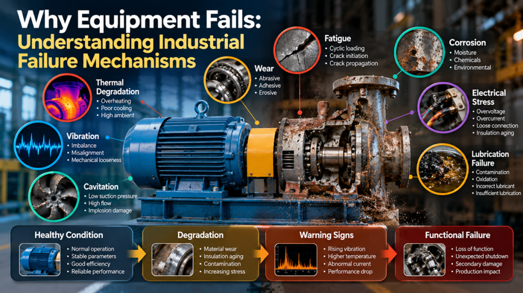
Industrial equipment rarely fails “suddenly.”
What appears to be a sudden failure is often the final stage of a degradation process that has been developing for hours, weeks, months, or even years.
A motor trips.
A bearing seizes.
A cable insulation breaks down.
A pump loses capacity.
A transmitter begins drifting.
A valve becomes difficult to operate.
A heat exchanger leaks.
From an operational perspective, these events may look like isolated equipment failures.
From a reliability perspective, however, each failure is the end result of a physical failure mechanism.
Understanding that mechanism changes how engineers and technicians approach maintenance.
Instead of asking only:
“What failed?”
they begin asking:
“How did it fail?”
“What mechanism created the damage?”
“What conditions accelerated the degradation?”
“Were there detectable warning signs?”
“Could the same mechanism be developing elsewhere?”
This shift—from replacing failed components to understanding failure mechanisms—is fundamental to reliability engineering.
Failure Is Usually a Process, Not an Event
Imagine a motor bearing that eventually fails.
The final event may be:
Bearing seizure
But the failure process may actually look like this:
Lubrication contamination
→ lubricant film degradation
→ increased friction
→ localized heating
→ surface damage
→ vibration increase
→ accelerated wear
→ bearing seizure
The seizure is only the final event.
The actual failure mechanism began much earlier.
This distinction matters because maintenance performed only at the final stage becomes reactive.
Maintenance based on the degradation mechanism can become predictive.
Failure Mode, Failure Mechanism, and Root Cause Are Not the Same
These terms are often used interchangeably, but they describe different things.
Consider an electric motor.
Failure Mode
The motor cannot operate.
Examples might include:
- failure to start,
- unexpected trip,
- reduced output,
- excessive vibration,
- overheating.
The failure mode describes what happened to the function.
Failure Mechanism
The physical process that caused deterioration.
Examples include:
- insulation thermal degradation,
- bearing fatigue,
- corrosion,
- abrasion,
- electrical tracking,
- lubrication breakdown.
The failure mechanism explains how the damage developed.
Root Cause
The underlying condition that allowed or initiated the mechanism.
Examples:
- inadequate lubrication practice,
- cooling system blockage,
- incorrect motor loading,
- improper installation,
- moisture ingress,
- poor alignment,
- incorrect protection settings,
- contaminated environment.
The root cause explains why the mechanism was allowed to occur.
A good failure investigation attempts to connect all three.
Failure Mode
→ Failure Mechanism
→ Root Cause
ISO 14224 reflects this type of structured reliability thinking by defining standardized categories for equipment, failure data, failure causes, consequences, and maintenance information, helping organizations build a consistent reliability language.
Why Understanding Failure Mechanisms Matters
If maintenance focuses only on replacing failed parts, the same failures can continue indefinitely.
Consider a motor bearing replaced every six months.
Replacing the bearing may restore equipment function.
But if the real mechanism is caused by shaft misalignment, the new bearing will experience the same stress.
The cycle becomes:
Bearing failure
→ replacement
→ temporary recovery
→ bearing failure again
The maintenance organization becomes very busy.
Reliability does not improve.
A mechanism-based approach instead asks:
- Why is the bearing experiencing abnormal load?
- Is lubrication adequate?
- Is contamination entering the bearing?
- Is alignment correct?
- Is there electrical discharge through the bearing?
- Is the operating temperature accelerating lubricant degradation?
The objective changes from:
repairing the failure
to:
removing the mechanism that creates the failure.
1. Wear
Wear is one of the most common industrial degradation mechanisms.
It occurs when material is progressively removed from interacting surfaces.
Several different forms of wear exist.
Abrasive Wear
A hard surface or contaminant physically removes material from another surface.
Common examples include:
- contaminated bearings,
- hydraulic systems containing particles,
- pump components exposed to solids,
- gears operating with contaminated lubrication.
Particles can act like microscopic cutting tools.
The damage may begin slowly but accelerate as additional debris is generated.
Adhesive Wear
Two surfaces under load may experience localized contact and material transfer.
Poor lubrication increases the risk.
Typical applications include:
- bearings,
- gears,
- sliding mechanisms,
- valve stems.
Erosive Wear
Material is gradually removed by high-velocity particles or fluid flow.
Examples include:
- pump impellers,
- piping bends,
- control valves,
- turbine components.
The important point is that “wear” is not one single mechanism.
Different wear mechanisms require different corrective actions.
2. Fatigue
Fatigue occurs when repeated cyclic loading gradually creates and propagates cracks.
The applied stress does not necessarily need to exceed the material’s ultimate strength.
Repeated cycles can progressively damage the material.
A simplified sequence is:
Repeated stress
→ microcrack initiation
→ crack propagation
→ reduced effective cross-section
→ final fracture
Fatigue can affect:
- shafts,
- gears,
- bearings,
- rotating equipment,
- structural components,
- electrical connections subjected to thermal cycling.
The final fracture may appear sudden.
But the crack may have been growing for months.
3. Bearing Fatigue
Rolling-element bearings experience repeated contact stresses.
Over time, fatigue damage may develop beneath or at the rolling surfaces.
Eventually, surface material may begin breaking away.
This may appear as:
- pitting,
- flaking,
- spalling.
The process can lead to:
- increasing vibration,
- increased noise,
- additional particle generation,
- higher temperatures,
- progressive bearing deterioration.
This illustrates why vibration monitoring is valuable.
The objective is not simply to detect “high vibration.”
The objective is to detect evidence that a physical degradation mechanism is developing.
4. Lubrication Failure
Lubrication problems are responsible for many mechanical failures.
Lubricant performs several important functions:
- separates surfaces,
- reduces friction,
- removes heat,
- carries contamination,
- protects against corrosion.
Problems can occur from:
- insufficient lubrication,
- excessive lubrication,
- incorrect lubricant,
- contamination,
- lubricant oxidation,
- incorrect viscosity,
- incompatible lubricant mixing.
Consider a bearing.
Insufficient lubrication
→ thinner lubricant film
→ increased metal contact
→ higher friction
→ higher temperature
→ faster lubricant degradation
→ accelerated bearing damage
Notice the feedback loop.
Higher temperature damages the lubricant.
Damaged lubricant increases friction.
Friction creates more heat.
The mechanism becomes self-accelerating.
5. Corrosion
Corrosion is an electrochemical degradation mechanism that can progressively reduce material integrity.
Industrial environments can accelerate corrosion through:
- humidity,
- chemicals,
- salts,
- process contaminants,
- elevated temperature,
- condensation.
Corrosion can affect:
- piping,
- vessels,
- cable trays,
- electrical panels,
- terminals,
- grounding systems,
- instrumentation enclosures.
Corrosion does not only threaten mechanical integrity.
In electrical systems, corrosion can increase contact resistance.
That can create another failure chain:
Corrosion
→ increased contact resistance
→ localized heating
→ insulation damage
→ connection failure
One mechanism can therefore trigger another.
6. Thermal Degradation
Temperature is one of the most powerful accelerators of equipment degradation.
Many industrial materials are temperature-sensitive.
Examples include:
- electrical insulation,
- lubricants,
- seals,
- electronics,
- polymers.
For an electric motor, excessive temperature may result from:
- overload,
- low voltage,
- voltage imbalance,
- blocked cooling passages,
- high ambient temperature,
- excessive starts,
- bearing problems.
Higher temperature accelerates insulation aging.
Therefore overheating should not be viewed only as a symptom.
It is itself a degradation mechanism.
7. Electrical Insulation Aging
Electrical insulation deteriorates under multiple stresses.
Common contributors include:
Thermal Stress
Excessive operating temperature accelerates chemical aging.
Electrical Stress
Voltage stress can contribute to partial discharge, tracking, and insulation breakdown.
Mechanical Stress
Vibration and movement may damage insulation systems.
Environmental Stress
Moisture, chemicals, contamination, and dust can reduce insulation reliability.
These stresses may interact.
For example:
Loose winding
→ vibration
→ insulation abrasion
→ reduced dielectric strength
→ partial discharge
→ insulation breakdown
The final motor fault may appear electrical.
But the initiating mechanism may have been mechanical.
8. Partial Discharge
Partial discharge is a localized electrical discharge occurring within or around insulation without completely bridging the insulation system.
It can occur in:
- high-voltage motors,
- generators,
- switchgear,
- cables,
- transformers.
Repeated discharge activity can gradually damage insulation.
The progression can be:
Insulation defect
→ localized electrical field enhancement
→ partial discharge
→ progressive insulation erosion
→ increased discharge activity
→ eventual insulation failure
This is another example where a catastrophic electrical failure may be preceded by a detectable degradation mechanism.
9. Loose Electrical Connections
A loose connection may seem like a simple maintenance issue.
But consider the physical mechanism.
Contact resistance increases.
The generated heat approximately follows:
P = I²R
As resistance increases, heat generation increases.
This can lead to:
Loose connection
→ increased resistance
→ localized heating
→ oxidation
→ further resistance increase
→ insulation degradation
→ connection failure
This positive feedback mechanism explains why loose connections can deteriorate rapidly once heating begins.
Thermography can therefore be useful not merely for detecting “hot spots,” but for identifying the thermal signature of developing connection problems.
10. Electrical Overstress
Electrical components can fail when exposed to conditions beyond their design capability.
Examples include:
- overvoltage,
- overcurrent,
- transient surges,
- short circuits,
- incorrect voltage,
- harmonic distortion,
- excessive switching.
Electrical overstress may damage:
- semiconductor devices,
- power supplies,
- PLC modules,
- VFD components,
- instrumentation.
The visible failed component may not be the true source of the event.
A damaged electronic board should therefore raise the question:
What electrical condition caused this component to experience abnormal stress?
11. Mechanical Misalignment
Misalignment occurs when connected rotating shafts are not correctly positioned relative to one another.
Possible consequences include:
- elevated vibration,
- coupling damage,
- bearing loading,
- seal deterioration,
- increased energy consumption.
The failure chain might be:
Misalignment
→ increased radial/axial forces
→ bearing stress
→ increased vibration and temperature
→ accelerated bearing degradation
→ bearing failure
Replacing only the bearing will not solve the problem.
The mechanism remains active.
12. Imbalance
Rotating imbalance occurs when the mass distribution around the rotational axis is uneven.
Possible causes include:
- material buildup,
- manufacturing variation,
- damaged impeller blades,
- missing balance weights,
- uneven wear.
Imbalance produces centrifugal forces that increase with rotational speed.
These forces can create:
- vibration,
- bearing loading,
- looseness,
- fatigue.
Again, vibration itself is not always the failure.
It may be the observable consequence of an underlying mechanism.
13. Cavitation
Cavitation commonly affects pumps and other fluid equipment.
When local fluid pressure falls below vapor pressure, vapor bubbles can form.
When those bubbles collapse in higher-pressure regions, they can generate intense localized forces.
Over time, this can cause:
- surface pitting,
- impeller damage,
- vibration,
- noise,
- reduced pump performance.
Possible contributors include:
- inadequate suction pressure,
- excessive flow,
- suction restrictions,
- incorrect pump selection,
- high fluid temperature.
Replacing the impeller without correcting hydraulic conditions will not eliminate the mechanism.
14. Contamination
Contamination frequently acts as a hidden accelerator of equipment degradation.
Examples include:
- particles in lubricants,
- moisture in electrical insulation,
- dust in cooling systems,
- chemicals entering enclosures,
- conductive contamination on circuit boards.
Contamination can initiate several mechanisms simultaneously.
For example:
Dust accumulation in electrical cabinet
→ reduced cooling
→ higher component temperature
→ accelerated electronic aging
If the dust is conductive, it may also increase the risk of tracking or short circuits.
15. Environmental Degradation
Industrial equipment operates in environments that may include:
- heat,
- humidity,
- dust,
- chemicals,
- vibration,
- UV exposure,
- salt atmosphere.
Equipment that performs reliably in one environment may fail rapidly in another.
This means reliability cannot be evaluated independently from operating context.
The same electrical enclosure may behave very differently in:
- an air-conditioned control room,
versus
- an outdoor petrochemical installation exposed to heat, rain, humidity, and process chemicals.
16. Human-Induced Failure
Not every degradation mechanism originates from the equipment itself.
Failures can also be introduced through:
- incorrect installation,
- incorrect torque,
- incorrect wiring,
- improper lubrication,
- wrong spare parts,
- incorrect settings,
- poor commissioning,
- incomplete maintenance.
For example:
Terminal incorrectly torqued
→ loose connection
→ resistance increase
→ thermal cycling
→ further loosening
→ severe overheating
The visible failure may appear to be an equipment problem.
The actual root cause may have originated during installation or maintenance.
Multiple Failure Mechanisms Often Interact
Real industrial failures are rarely as simple as textbook diagrams.
Consider this motor example:
Shaft misalignment
→ excessive bearing load
→ increased friction
→ bearing temperature rise
→ lubricant degradation
→ accelerated wear
→ vibration increase
→ additional mechanical stress
→ bearing failure
Several mechanisms interact:
- mechanical loading,
- friction,
- thermal degradation,
- lubrication breakdown,
- wear.
This explains why simply identifying one abnormal parameter may be insufficient.
Reliability engineers need to understand the entire degradation pathway.
The Failure Mechanism Chain
A practical way to investigate equipment failure is to construct a chain:
1. Initiating Condition
What started the degradation?
Examples:
- contamination,
- overload,
- poor installation,
- abnormal process condition.
2. Failure Mechanism
What physical process created damage?
Examples:
- fatigue,
- corrosion,
- wear,
- overheating,
- electrical tracking.
3. Degradation
How did equipment condition deteriorate?
Examples:
- crack growth,
- insulation weakening,
- bearing surface damage,
- resistance increase.
4. Detectable Symptoms
What indicators appeared?
Examples:
- vibration,
- temperature,
- current,
- noise,
- partial discharge,
- oil debris.
5. Functional Failure
What function could no longer be performed?
Examples:
- pump cannot deliver required flow,
- motor cannot operate,
- valve cannot control process,
- transmitter produces unreliable measurement.
This chain connects reliability engineering with condition monitoring.
Failure Mechanisms Create Detectable Signals
An important reliability principle is that many degradation mechanisms create measurable changes before functional failure occurs.
For example:
| Failure Mechanism | Potential Indicator |
|---|---|
| Bearing degradation | Vibration, temperature |
| Lubricant contamination | Oil analysis |
| Loose electrical connection | Thermal imaging, voltage drop |
| Motor overload | Current trend, temperature |
| Insulation degradation | Insulation resistance, PD activity |
| Corrosion | Thickness inspection, visual inspection |
| Pump cavitation | Vibration, noise, pressure |
| Filter blockage | Differential pressure |
| Fouling | Thermal efficiency, pressure drop |
This is the foundation of condition-based maintenance.
ISO 17359 provides general guidance for establishing machine condition-monitoring programs and applies across machine types.
From Failure Detection to Failure Prediction
Traditional maintenance often asks:
Has something failed?
Condition monitoring asks:
Is degradation occurring?
Predictive maintenance attempts to go further:
How quickly is the degradation progressing?
This creates a maturity progression:
Reactive Maintenance
Failure occurs → repair equipment.
↓
Preventive Maintenance
Perform maintenance periodically.
↓
Condition-Based Maintenance
Perform maintenance when condition indicates degradation.
↓
Predictive Maintenance
Estimate how degradation is evolving and when intervention will be required.
Understanding failure mechanisms is essential as organizations move up this maturity curve.
Without mechanism knowledge, monitoring becomes little more than collecting data.
Data Is Valuable Only When Connected to Physics
Modern industrial facilities can collect enormous quantities of information.
Examples include:
- vibration,
- temperature,
- current,
- voltage,
- pressure,
- flow,
- lubrication condition,
- process variables.
But a sensor does not automatically create reliability.
Suppose motor bearing temperature increases from:
65°C → 69°C → 74°C → 81°C
The important question is not simply:
“Is 81°C high?”
A reliability engineer may ask:
- Is load changing?
- Is vibration also increasing?
- Is ambient temperature stable?
- Has lubrication recently been performed?
- Is temperature increasing only on the drive-end bearing?
- Is motor current normal?
The objective is to connect data with a physical hypothesis.
**Data
- Equipment Knowledge
- Failure Physics
= Useful Diagnosis**
Why Trend Matters More Than a Single Number
A single measurement provides condition at one moment.
A trend reveals development.
Consider vibration.
Scenario A
Vibration = 7 mm/s and has remained stable for two years.
Scenario B
Vibration increased:
2 → 3 → 4 → 5 → 7 mm/s
during the previous month.
Even though both currently measure 7 mm/s, the risk interpretation may be very different.
The second case contains evidence of active degradation.
This is why reliability monitoring should consider:
- absolute value,
- rate of change,
- operating condition,
- historical baseline.
Failure Mechanisms and the P-F Concept
A useful reliability concept is the interval between a potential failure and a functional failure.
A potential failure occurs when degradation becomes detectable.
Functional failure occurs when equipment can no longer perform its required function.
For example:
Bearing defect begins
↓
Vibration signature becomes detectable
↓
Temperature increases
↓
Noise becomes noticeable
↓
Bearing failure
The earlier the degradation can be detected, the more time maintenance teams have to respond.
This creates opportunities to:
- plan maintenance,
- obtain spare parts,
- schedule downtime,
- prevent secondary damage.
Not Every Failure Should Be Prevented the Same Way
An important reliability principle is that maintenance strategy should depend on the nature of the failure.
Some failures can be managed through:
- scheduled replacement,
- condition monitoring,
- functional testing,
- redesign,
- run-to-failure.
Reliability-centered maintenance uses structured analysis of equipment functions, functional failures, failure modes, consequences, and applicable maintenance policies. IEC 60300-3-11 provides guidance for developing failure-management policies using RCM analysis techniques across industries.
The objective is not to perform more maintenance.
It is to apply the right failure-management strategy.
Over-Maintenance Can Also Create Failure
More maintenance does not automatically mean higher reliability.
Maintenance interventions themselves introduce risk.
For example:
- terminals may be improperly retightened,
- connectors may be damaged,
- contaminants may enter equipment,
- alignment may change,
- wiring errors may be introduced,
- incorrect lubrication may be applied.
This is sometimes called maintenance-induced failure.
Therefore maintenance frequency should be based on technical reasoning rather than the assumption that:
“More frequent maintenance is always better.”
A Practical Failure Investigation Framework
When equipment fails, consider asking the following sequence.
Step 1 — Define the Functional Failure
What required function was lost?
Step 2 — Identify the Failure Mode
What observable failure occurred?
Step 3 — Inspect the Damage
What physical evidence exists?
Examples:
- discoloration,
- cracks,
- wear marks,
- corrosion,
- burned insulation,
- deposits,
- looseness.
Step 4 — Identify the Mechanism
What physical process could create this damage pattern?
Step 5 — Review Operating History
Look at:
- load,
- temperature,
- vibration,
- alarms,
- maintenance history,
- process conditions.
Step 6 — Identify Contributing Factors
Examples:
- environment,
- installation,
- operation,
- maintenance,
- design.
Step 7 — Determine Root Cause
Why was the failure mechanism allowed to develop?
Step 8 — Define Corrective Action
Correct the cause—not merely the damaged component.
Step 9 — Look for Systemic Risk
Ask:
Could the same mechanism exist on similar equipment?
This is where failure investigation creates organizational value.
Example: Repeated Motor Bearing Failure
Suppose a motor bearing repeatedly fails every year.
Failure Mode
Motor unavailable due to bearing damage.
Physical Evidence
- severe bearing wear,
- elevated drive-end vibration,
- increased temperature before failure.
Possible Mechanisms
- inadequate lubrication,
- shaft misalignment,
- excessive belt tension,
- electrical bearing current.
Simply replacing the bearing does not determine which mechanism is active.
Additional evidence may show:
- lubricant condition is acceptable,
- alignment is outside tolerance,
- vibration pattern is consistent with misalignment.
The failure chain becomes:
Poor alignment
→ excessive bearing loading
→ increased stress and friction
→ accelerated bearing degradation
→ bearing failure
The corrective action should therefore include alignment improvement.
Not only bearing replacement.
Example: Burned Electrical Terminal
Suppose a cable termination is severely burned.
The failure mode is obvious.
But the mechanism requires investigation.
Possible chain:
Insufficient tightening torque
→ increased contact resistance
→ I²R heating
→ oxidation
→ resistance increases further
→ insulation degradation
→ thermal failure
The maintenance lesson is different from simply:
Replace the damaged terminal.
Potential corrective actions may include:
- reviewing installation torque,
- checking similar terminations,
- improving inspection practices,
- applying thermographic monitoring where appropriate.
One failure can reveal a systemic reliability risk.
Why Good Failure Data Matters
Organizations often store maintenance history such as:
“Motor repaired.”
This provides very little reliability information.
A better record might contain:
Failure Mode: Motor tripped on overload
Mechanism: Bearing degradation
Cause: Lubrication contamination
Action: Bearing replaced and lubrication system improved
Structured failure records allow organizations to identify patterns across assets.
ISO 14224 specifically emphasizes standardized reliability and maintenance data—including equipment, failure, and maintenance information—to support consistent analysis and communication of operational experience.
Over time, this allows questions such as:
- Which equipment fails most frequently?
- Which mechanisms dominate?
- Which root causes create the most downtime?
- Which maintenance activities actually reduce recurrence?
From Maintenance History to Reliability Intelligence
Imagine a plant with 500 motors.
Individual work orders may look unrelated.
But after categorization, engineers might discover:
35% — bearing-related
25% — insulation-related
15% — connection-related
10% — contamination
15% — other
The organization can then investigate deeper.
Perhaps most bearing failures occur in one process area.
Perhaps most insulation failures occur on motors operating above design temperature.
Perhaps connection failures are concentrated after major shutdown work.
Failure data becomes reliability intelligence.
And reliability intelligence drives targeted improvement.
Failure Mechanisms Should Influence Maintenance Strategy
Different mechanisms require different monitoring methods.
For example:
Bearing degradation
Possible monitoring:
- vibration,
- temperature,
- ultrasound,
- lubricant analysis.
Electrical connection deterioration
Possible monitoring:
- thermography,
- voltage-drop measurement,
- visual inspection.
Insulation deterioration
Possible monitoring:
- insulation resistance,
- polarization index,
- partial-discharge analysis,
- dielectric testing where applicable.
Lubricant degradation
Possible monitoring:
- viscosity,
- particle count,
- moisture,
- wear debris.
Good maintenance therefore begins with:
What failure mechanism are we trying to detect or control?
not:
What inspection have we always performed?
The Reliability Mindset
A reactive maintenance organization sees failure as:
“Something broke.”
A reliability-focused organization sees failure as:
“A physical degradation mechanism developed until the equipment could no longer perform its required function.”
That difference changes the questions people ask.
Instead of:
Who will repair it?
they also ask:
Why did it happen?
How long was the mechanism developing?
Could we have detected it earlier?
Where else could the same mechanism exist?
What should change in our maintenance strategy?
Those questions transform failure from an operational disruption into an engineering learning opportunity.
The Most Important Lesson
Equipment does not fail because it “decides” to stop working.
Failure follows physics.
Materials fatigue.
Surfaces wear.
Lubricants degrade.
Electrical insulation ages.
Connections develop resistance.
Corrosion removes material.
Heat accelerates degradation.
Contaminants interfere with designed operating conditions.
Mechanical forces produce stress.
Failure mechanisms are therefore understandable.
And if they are understandable, many of them are also detectable, manageable, and preventable.
The goal of maintenance should not simply be:
Repair equipment after it fails.
The more advanced objective is:
Understand how equipment fails, detect the mechanism early, and intervene before functional failure occurs.
That is the transition from maintenance to reliability engineering.
Build Reliability Competency, Not Just Maintenance Experience
Every failure should generate knowledge.
When equipment fails, do not record only:
“Bearing replaced.”
Document:
- what failed,
- how it failed,
- what mechanism caused the damage,
- what condition initiated the mechanism,
- what evidence supports the conclusion,
- what corrective action was implemented,
- and how recurrence will be prevented.
Over time, professionals who think this way develop a deeper understanding of industrial assets.
They stop seeing equipment as collections of replaceable components.
They begin seeing systems governed by physical degradation processes.
And that shift is one of the foundations of professional reliability engineering.
References
- ISO 14224:2016 — Petroleum, petrochemical and natural gas industries — Collection and exchange of reliability and maintenance data for equipment. The standard remains current after confirmation and establishes structured approaches to equipment, failure and maintenance data.
- ISO 17359:2018 — Condition monitoring and diagnostics of machines — General guidelines. Provides general guidance for establishing machine condition-monitoring programs.
- IEC 60300-3-11:2009 — Dependability management — Application guide — Reliability centred maintenance. Provides guidance for developing failure-management policies using RCM techniques.